



 92 / 105

91
and length than steel wheel inner nuts (See TMC RP
217A,
Attaching Hardware for Disc Wheels.
)
6. Separate all frozen cap nuts prior to reinstalling the
wheel. Do not attempt to reapply wheels that come
off with the inner cap nut frozen to the outer cap nut.
Each nut must be reinstalled properly with each nut
tightened to the proper torque level.
7.
Never lubricate wheel or nut ball seats or mount-
ing faces.
If lubrication is desired, it should be used
sparingly only on the threads of the studs and/or nuts.
If lubrication is used, consult the wheel manufacturer
for torque recommendations.
8. Slide the front wheel or inner dual wheel over the
studs being careful not to damage the stud threads.
Lift the wheel to center one stud within its bolt hole
while installing an inner nut finger tight. Repeat with
another nut about 180 degrees away from the first.
Install the remaining nuts. Snug up nuts to about 50
ft. lbs. in the sequence shown in Figure 2. Do tighten
then fully until all have been seated. This procedure
will permit the uniform seating of nuts and ensure the
even, face to face contact of the wheels against the
hub or drum. Tighten the nuts to the recommended
mounting torque (see Table 1) using the same criss-
cross tightening sequence.
9. Place the outer dual wheel over the ends of the inner
nuts and install 2 outer nuts 180 degrees apart finger-
tight to locate the wheel. Install the remaining nuts
and tighten to 50 ft. lbs. using a crisscross sequence
as shown in
Figure 2
. Finally tighten the outer nuts
to the recommended torque (see
Table 1
) using the
same sequence.
10. After a wheel assembly has been installed, recheck
the torque level between 50 and 100 miles of opera-
tion and retighten if necessary to the recommended
torque using the proper sequence. To check and re-
torque an inner nut, it is necessary to loosen the outer
nut first, and then tighten the inner nut. Finally, the
outer nuts must be retightened to the proper level.
11. It is recommended that a torque check be made as
part of a vehicles scheduled maintenance program or
at 10,000 mile intervals whichever comes first. Indi-
vidual fleet experience may dictate shorter intervals
or allow longer intervals.
12. If air wrenches are used, they must be periodically
calibrated for proper torque output. Use a torque
wrench to check the air wrench output. If output is not
correct, take the necessary steps to adjust output.
SPOKE WHEEL/DEMOUNTABLE RIM SYSTEM IN-
STALLATION PROCEDURES
1. Ensure that the correct spacer band, rim, and clamp
combinations are being used for the application.
Check all parts for damage. Ensure that studs, nuts,
clamps and 28 degree mounting surfaces of the cast
spoke wheel and rim are sound, clean and free from
grease. Clean the cast spoke wheel with a wire brush
if scale is present. The spacer band should be clean
and free from distortion.
2. Replace any damaged or distorted part. Do not weld,
heat, or braze.
3. Install the rim after the tire is inflated. Multi-piece rims
may distort at high inflation and become difficult to
slip onto the cast spoke wheel. If this occurs deflate
the tire to not less than 80% of the recommended
inflation until the rim is mounted on the truck. If dif-
ficulties still exist, contact the rim manufacturer for
recommendations. Always adhere to OSHAstandard
No. 29 CFR, Part 1910.177 “Servicing Single-Piece
and Multi-Piece Rims/Wheels” and TMC RP 209B,
Wheel Installation & Maintenance
1
6
4
2
5
3
1
4
2
5
3
1
6
4
2
5
3
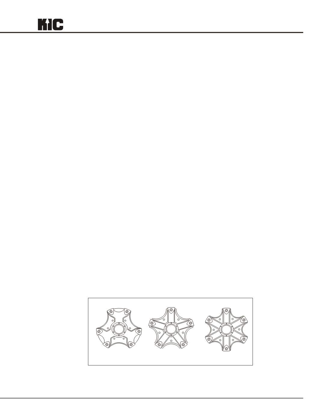
3 Spoke
5 Spoke
6 Spoke
Figure 3: Nut Tightening Sequence for Spoke Wheels
TMC Recommended Practices: Used by permission
TMC RP 222B © 2003 – TMC/ATA – Reprinted with Permission