



 91 / 105

90
then apply nuts finger-tight on the remaining studs.
Snug the nuts to about 50 ft. lbs. following a crisscross
sequence as shown in
Figure 1.
Finally, tighten all
the nuts to the recommended torque (see
Table 1
)
using the same crisscross sequence.
11. After the wheels are installed, check to see that both
wheels are still seated on to the pilots and are flat
against the drum. This can be done by inspecting the
seating of the wheels on all four pilots and by turning
the wheels and checking for irregularity of the wheel
assembly.
12. After a wheel assembly has been installed, recheck
the torque level between 50 and 100 miles of opera-
tion and retighten if necessary to the recommended
torque using the proper sequence. It is recommended
that a torque check be made as part of a vehicle’s
scheduled maintenance program or at 10,000 mile
intervals, whichever comes first. Individual fleet ex-
perience may dictate shorter intervals or allow longer
intervals.
13. If air wrenches are used, they must be periodically
calibrated for proper torque output. Use a torque
wrench to check the air wrench output. If output is not
correct, take the necessary steps to adjust output.
DISC WHEEL INSTALLATION PROCEDURE –
STUD PILOTED DISC WHEEL SYSTEM.
1. Check all parts for damage including wheels and
rings. Ensure that studs, nuts and mounting faces of
hubs, drums and wheels are free of dirt and grease.
The hub or drum mounting face must be cleaned
and kept flat. Clean hub or drum surface with a wire
brush if rust or debris is present. Note the condition of
the hub and drum. Replace them if worn or cracked
bolt holes or a worn hub or drum face are evident .
If a heavy duty ball seat (1-3/16” spherical radius)
system is used, make sure the wheels are proper for
the vehicle. Never mix hub-piloted disc wheels and
hubs with ball-seat disc wheels and hubs. The result
could be loss of torque, a cracked wheel or possible
wheel loss.
2. Wire brush at the base of each stud as well as the
threads to remove any rust or foreign material which
could bind up the wheel nuts.
3. Check for damaged studs. Replace any parts which
exhibit wear or damage. Ensure replacement studs
are the proper ones for the system used. Stud break-
age can result if the wrong studs are used.
If a stud is broken, replace it and the stud on each
side of the broken one. If 2 or more studs are broken,
replace them all. Use a press to install studs and be
sure the hub flange is supported. Aluminum hubs
require different stud installation procedures. Consult
the manufacturer for recommendations. Stud heads
can be bent from hammer blows which will prevent
the stud from seating properly and can result in stud
failure.
4. Check the wheel for damage, elongated bolt holes,
wear, corrosion, cracks around bolt holes or center
hole or torch cuts and replace as necessary. If slight
burrs have been raised around the ball seats, use a
file to remove them. Be sure not to cut into the flat
surface of the wheel mounting face. Wire brush inner
and outer cap nuts if rust accumulation is evident. If
threads are damaged or corrosion is heavy, discard
nuts. Also discard nuts that show damage or wear
to ball seats or hex areas.
5. Be certain you have correct fasteners. Nuts used in
the hub piloted system cannot be used in the stud
piloted system. Single aluminum wheels on ¾” stud
use different nuts than steel wheels. Dual aluminum
wheels require special inner nuts with greater strength
Wheel Installation & Maintenance
1
2
3
4
5
6
7
8
9
10
1
2
3
6
4
5
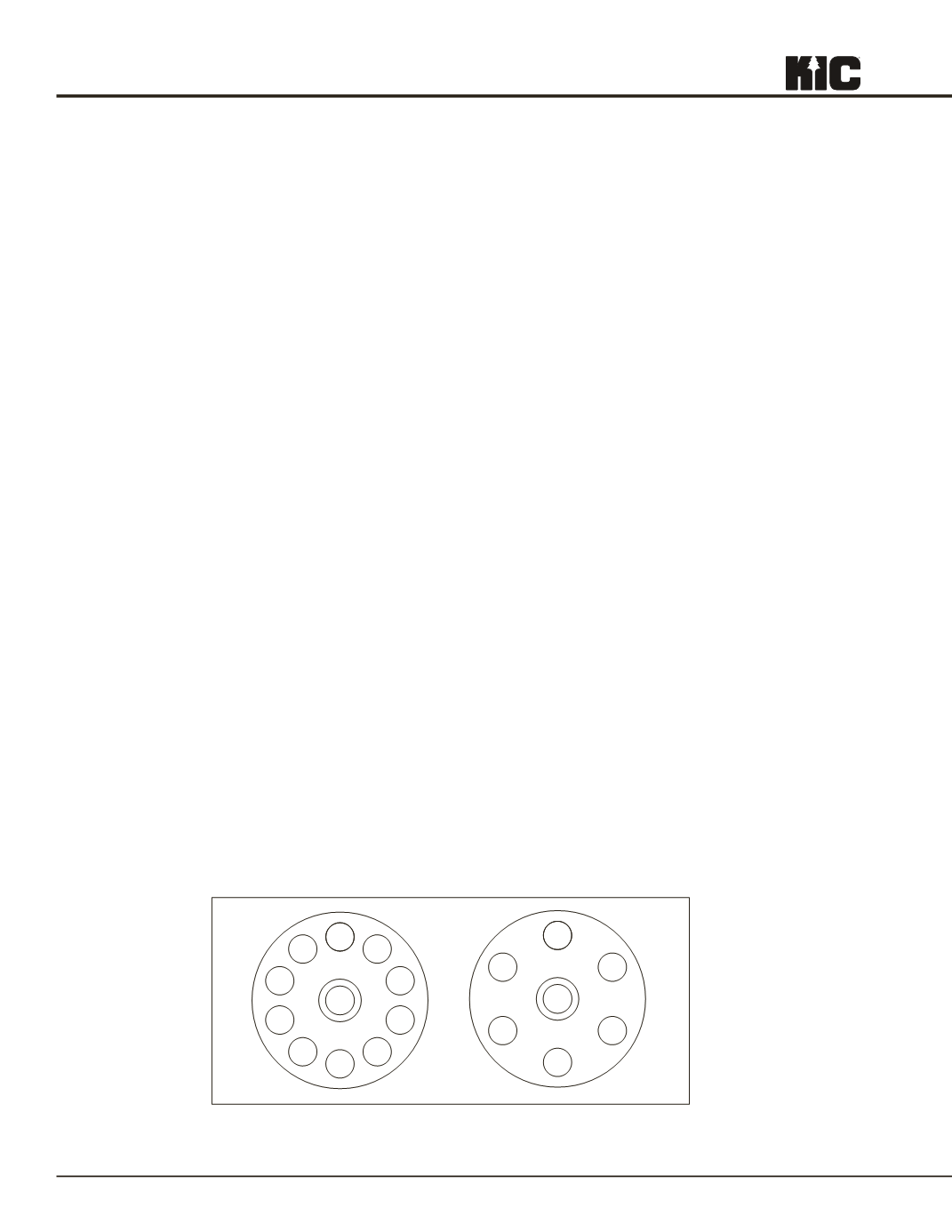
Figure 2: Nut Tightening Sequence for Stud Piloted Disc Wheels
TMC Recommended Practices: Used by permission
TMC RP 222B © 2003 – TMC/ATA – Reprinted with Permission